Search within website

Sample paper 3

1.  What are wind energy farms?

2.  What is meant by potential difference between two points?

3.  How much energy will an electric bulb draw from a 220 V source, if the resistance of the bulb-filament is 1200 ohms?

4. What is electromagnetic induction?

5. In what way can the magnitude of induced current be increased?

6. Calculate the electrical energy consumed by a 1200 W toaster in 20 minutes.

7. Biomass has been used as fuel since ancient times, how has it been modified to function as a more efficient fuel in the recent past.

8. Two identical resistors, each of resistance 20 ohms are connected (i) in parallel (ii) in series, in turn, to a battery of 10V. Calculate the ratio of power consumed in the combination of resistors in the two cases.

9. Two resistors of resistances 3 ohms and 6 ohms respectively are connected to a battery of 6 V so as to have
(a)    Minimum resistance,    (b) minimum current
(i)  How will you connect the resistances in each case?
(ii) Calculate the strength of the current in the circuit in both cases.

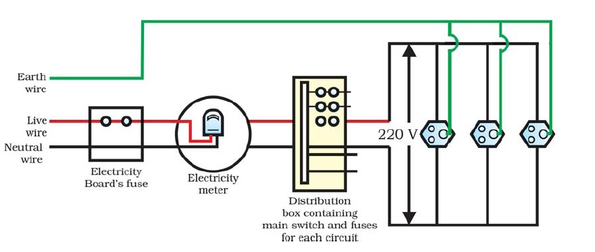
10. Explain what is short circuiting and overloading in an electric supply?

11. Why can’t two magnetic field lines cross each other?

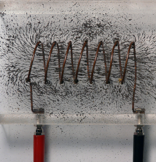
12. Draw the magnetic field lines (including field directions) of the magnetic field due to a long straight solenoid. What important property of this field is indicated by this field line pattern? Name any two factors on which the magnitude of the magnetic field due to this solenoid depends.

13. State the rule to determine the direction of a
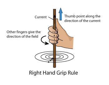
(i)  Magnetic field produced around a straight conductor carrying current.
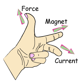
(ii) Force experienced by current – carrying straight conductor placed in a magnetic field which is perpendicular to it.
(iii) Current induced in a coil due to its rotation in a magnetic field.

14. Differentiate between AC and DC. Write one advantage of AC over DC.


Domestic Electric Circuit

Domestic Electric Circuit


1.     Household electric supply consists of 3 types of wire. Live wire (red insulation cover), neutral wire (black insulation cover) and earth wire (green insulation cover)
2.    The potential difference between neutral and live wire is 220V.
3.    In household circuit system, two type of circuit are used. One of 15 A for appliances with higher power ratings and the other of 5 A ratings for bulbs etc.
4.    In domestic circuit, different appliances are connected in parallel combination. This ensures that if one appliance is switched ‘on’ or ‘off’, the others are not affected.
5.    The earth wire is used as a safety measure, especially for those appliances that have a metallic body.


Working of earth wire 

The metallic body is connected to the earth wire, which provides a low resistance-conducting path for the current. It ensures that any leakage of current to the metallic body of the appliance will flow to the earth only and the user may not get a severe shock.
Watch the video below to more explanation on working of earth wire.


Short circuit

It means that the two wires live and neutral have come in contact with each other. This may happen either due to their insulation have been damaged or due to a fault in the appliance. In such a case, the resistance of the circuit decreases to a very small value. According to Ohm’s law, the current increases enormously. It may results in spark at the place of short circuit, which may even cause fire. Sometimes, the current also increase due to overloading of the circuit.


Overloading

It is a situation when too many appliances are connected in the same circuit such that the overall current (sum of all the current used by all appliances) exceeds the current carrying capacity of the connecting wires. The wires cannot withstand such a high current and melt and may cause fire. 

The electric fuse

Electric fuse is used as safety device for the protection of electric circuits and appliances due to short circuiting or overloading of the circuit.. The electric fuse is a piece of wire having a very low melting point and high resistance.When a high current flows through the circuit due to short circuit or overloading, the fuse wire gets heated and melts. The circuit is broken and current stops flowing thus save the electric circuit and appliance form damage.

Capacities of fuse wire

The fuse for domestic purposes are rated as 1A, 2A, 3A, 5A, 10A and 15A.         

Characteristics of fuse wire

1.    Low melting point
2.    High resistance 

Fuse wire are made up of pure tin or made of an alloy of copper and tin.              


AC and DC

Alternating Current and Direct Current

Alternating Current (AC)
It is a current whose magnitude changes continuously and direction changes periodically.
The source of AC is AC generator.

In India mostly current is supplied in AC form. The frequency of AC in India is 50 Hz. It means AC changes direction every 1/100 of a second. In complete cycle of AC, it changes its direction twice.

Direct Current (DC)

It is a current whose magnitude is always constant and such a current flows in one direction only.
The source of DC are DC generators, cells, batteries etc

Advantage of AC over DC


1.  An alternating current (AC) can be transmitted to long distances without much power loss where as if direct current (DC) is supplied to long distance that most of its energy is wasted in the form of Joule’s heat.
2.  An alternating current (AC) can be step-up and step-down i.e. the voltage can be increased or decreased with the help of transformers whereas a DC can not step-up or step-down.


Electromagnetic Induction

Electromagnetic Induction

The process, by which a changing magnetic field in a conductor induces a current in it, is called Electromagnetic Induction.

Activity 1

1.    Take a coil of wire having many turns.
2.     Connect it to a sensitive galvanometer.
3.     Take a bar magnet and move the north pole of the magnet towards the coil.


Observation: you will observe that galvanometer will give a deflection in one direction (say left).

4.    Now move the north pole of the magnet away from the coil.

Observation: you will observe that galvanometer now give a deflection in opposite direction (now right)

**Similar effect will be observed if we use the south pole of the magnet in the above activity. But the direction of deflection will be reversed.

**Similar effect will be observed if we keep the magnet stationary and move the coil towards or away from the coil.

**When the coil and the magnet are both stationary, there is no deflection in the galvanometer.

Thus whenever there is a relative motion between the coil and the magnet, it induces a current in the coil.


Summary of the activity

POSITION OF THE MAGNET
DEFLECTION IN THE GALVANOMETER
Magnet at rest
No deflection in galvanometer
Magnet moves towards the coil
Deflection in galvanometer in one direction
Magnet is held stationary at same position (near the coil)
 No deflection in galvanometer
Magnet moves away from the coil
Deflection in galvanometer but in opposite direction
Magnet is held stationary at same position (away from the coil)
No deflection in galvanometer
Magnetic is held stationary inside the coil
 No deflection in galvanometer


Activity 2

1.    Take two different coils of copper wire having large number of turns (say 50 and 100 turns respectively). Insert them over a non-conducting cylindrical roll


2.    Connect the coil-1, having larger number of turns, in series with a battery and a plug key.
3.    Also connect the other coil-2 with a galvanometer as shown.
4.    Plug in the key. Observe the galvanometer.
Observation: You will observe that the needle of the galvanometer instantly jumps to one side and just as quickly returns to zero, indicating a momentary current in coil-2.
5.    Disconnect coil-1 from the battery.  Observe the galvanometer.


Observation: You will observe that the needle momentarily moves, but to the opposite side. It means that now the current flows in the opposite direction in coil-2.

Remark on activity 1 and 2

Thus form activity 1 and activity 2 it is clear that we can induce current in a coil either by moving it in a magnetic field or by changing the magnetic field around it. It is convenient in most situations to move the coil in a magnetic field.


The induced current is found to be the highest when

the direction of motion of the coil is at right angles to the magnetic field. In this situation, we can use a simple rule, Fleming's Right Hand Rule, to know the direction of the induced current.

Fleming’s Right Hand Rule


Hold the forefinger, the central finger and the thumb of the right hand perpendicular to each other so that the forefinger indicates the direction of the field, and the thumb is in the direction of motion of the conductor. Then, the central finger shows the direction of the current induced in the conductor.


Force on a current carrying wire

FORCE ON A CURRENT CARRYING CONDUCTOR PLACED IN A MAGNETIC FIELD

Any current carrying conductor when kept in magnetic field experiences a force. 
Watch a youTube video below to observe how a current carrying wire experiences a force when kept in a magnetic field. 


Video courtesy : Learn n hv fun YouTube Channel (A volunteer member of the website)


The direction of force is given by FLEMING’S LEFT HAND RULE.

ACTIVITY


1.   Take a small aluminium rod AB.
2.   Suspend it horizontally with the help of connecting wires from a stand.
3.   Place a strong horseshoe magnet in such a way that the rod is between the two poles with the field directed upwards.
4.   When current is passed in the rod from B to A, the rod gets displaced towards left.
5.   On reversing the direction of the current, the rod gets deflected towards right.

The deflection in the rod is caused by the force acting on the current carrying rod when placed in a magnetic field.
The displacement of the rod is largest (or the magnitude of the force is the highest) when the direction of current is at right angles to the direction of the magnetic field. In such a condition we can use a simple rule to find the direction of the force on the conductor.

FLEMING’S LEFT HAND RULE


Stretch the forefinger, the central finger and the thumb of your left hand mutually perpendicular to each other. If the forefinger shows the direction of the field and the central finger that of the current, then the thumb will point towards the force or direction of motion of the conductor.

FORCE ON A MOVING CHARGE PARTICLE IN A MAGNETIC FIELD


A current carrying conductor experiences a force when placed in a magnetic field. As current is simply flowing of charges, it implies that moving charged particles also experiences a force in a magnetic field.
The direction of the force on a moving positive charge is given by Fleming’s Left hand rule (discussed above).

Application of force experienced when placed in a magnetic field
Devices that use current-carrying conductors and magnetic fields include electric motor, loudspeakers, microphones and measuring instruments.


Solenoid

SOLENOID

A coil of many circular turns of insulated copper wire wrapped closely in the form of a cylinder is called a solenoid.


A solenoid

MAGNETIC FIELD DUE TO CURRENT IN A SOLENOID


1.   The magnetic field due to a solenoid is very much similar to that of a bar magnet. The pattern of the magnetic field lines around a current-carrying solenoid is similar to that of bar magnet. Just like a bar magnet, one end of the solenoid behaves as a magnetic north pole, while the other behaves as the South Pole. 
2.   The field lines inside the solenoid are in the form of parallel straight lines. This indicates that the magnetic field is the same at all points inside the solenoid. That is, the field is uniform inside the solenoid.

PRACTICAL USE OF SOLENOID

A strong magnetic field produced in a solenoid can be used to magnetize a piece of magnetic material when it is placed within the coil, which is carrying electric current.


ACTIVITY

1.   Take a iron nail.
2.   Wrap a coil of insulated copper wire on it.
3.   Connect the coil to a battery through a switch.
4.   As the current is passed through the coil, the nail, which acts as a core inside the solenoid, gets magnetized.
The magnet so formed is called an electromagnet.

ELECTROMAGNET

An electromagnet consists of a long coil of insulated copper wire wound on a soft iron core.


TEMPORARY MAGNET

If the core of the solenoid is taken of soft iron and electric current is passed through the solenoid, the soft iron core is temporarily magnetized which means when the current is switched off soft iron loses its magnetic properties. An electromagnet is a temporary magnet.

PERMANENT MAGNET

If the core of the solenoid is taken of carbon steel, chromium steel, cobalt and tungsten steel and certain alloys like Nipermag (alloy of iron, nickel, aluminium and titanium) and ALNICO (alloy of Aluminium, nickel and cobalt) and a strong electric current is passed through the coil then these materials become permanently magnetized.


Uses of permanent magnets


Such permanent magnets are used in microphones, loudspeakers, electric clocks, ammeter, voltmeter and speedometer, etc.


Circular coil

MAGNETIC FIELD DUE TO A CURRENT CARRYING CIRCULAR WIRE


Using Right Hand thumb rule, the magnetic field lines at every point of the circular wire are in the form of concentric circles with wire as the center. These magnetic field lines become larger and larger as we move away from the wire. Just at the center of the coil, magnetic field lines are almost straight. By applying Right hand rule, it is easy to check that every section of the wire contributes to magnetic field lines in the same direction within the loop.


Factors on which the magnetic field at the centre of the circular loop depends upon

1.   Directly proportional to the current flowing in the loop. 
2.   Inversely proportional to the radius of the circular wire.
3.   Directly proportional to the number of turns of the circular loop. This is because the current in each circular turn has the same direction, and the field due to each turn then just adds up.


Magnetic field due to current carrying straight conductor

Magnetic field around a current carrying straight conductor

Activity

1. Take a straight wire AB and pierced it through a horizontal cardboard such that wire AB is vertical.
2.   The ends of the wire AB are connected to a battery.
3.   Place some iron fillings on the cardboard.
4.   Switched the key on.
5.   Gently tap the cardboard.
6.   The iron fillings arrange themselves in concentric circles around the wire.
7.   This shows that magnetic field lines are concentric circles. The circles become larger and larger as we move away from the wire.

Watch a related video from YouTube.


Direction of field lines- Right Hand thumb rule

The direction of field lines due to a current carrying wire can be determined by using Right Hand Thumb Rule (Or Right Hand Grip Rule). 

Imagine that you are holding a current carrying wire in your right hand such that the thumb is stretched along the direction of the current, then, the fingers will wrap around the conductor in the direction of the field lines of the magnetic field.


Factors on which the magnetic field at a distance from the straight wire depends on

1.   Directly proportional to the current flowing in the wire.
2.   Inversely proportional to the distance from the wire.


Magnetic field and field lines

Oersted’s Experiment

(Relation between electricity and magnetism)

The first evidence of any connection between Electricity and magnetism was established by Hans Christian Oersted. He accidentally discovered that as he laid a wire carrying an electric current near a magnetic compass needle, it got deflected as if acted upon by a magnet.


This observation led to the discovery that when current passes through a conductor, magnetic field is produced around it.

Magnetic field

The space around a magnet or a current carrying conductor, in which the force of attraction or repulsion can be experienced, is called a magnetic field.

Demonstration of magnetic field lines (Iron-filings pattern)

1.  Take a bar magnet and placed it on a cardboard.
2.  Sprinkle some iron-fillings around the magnet.
3.  Tap the cardboard gently.
4.  Iron fillings arrange themselves in a pattern as shown in figure.


Conclusion: This pattern demonstrates that under the influence of magnetic field, the fillings align themselves along the magnetic field lines.

Tracing of magnetic field lines of a bar magnet

1.   Place a bar magnet on a sheet of paper.
2.   Bring the compass near the north pole of the magnet.
3.   The needle will deflect such that its south pole points towards North Pole of the bar magnet.
4.   Mark the position of two ends of needle.
5.   Move the compass so that its south end occupies the position previously occupied by the north end.
6.   Again mark the new position of ends of needle.
7.   Repeat step 5 and 6 till you reach the south pole of the magnet.
8.   Join the points marked to get a smooth curve, which represents a field line.


Magnetic field lines

Magnetic field lines are the imaginary lines used to represent a magnetic field. A field line is the path along which a hypothetical free north pole would tend to move. The direction of the magnetic field at a point is given by the direction that a north pole placed at that point would take.

Properties of Magnetic field lines

1.   Outside the bar magnet, the magnetic field lines originate from the north pole of a magnet and end at its south pole.
2.   Inside the bar magnet, field lines move from South Pole of the magnet to the North Pole.
3.   Magnetic field lines always form closed curves.
4.   The regions, where field lines are closer, the field is strong and the regions, where the field lines are farther apart, the field is weak.
5.   The direction of the magnetic field is taken to be the direction in which a north pole of the compass needle moves inside it.
6.   The magnetic field lines never cut each other. In case, two field lines intersect each other at a point, then it will mean that at the point of intersection, the magnetic needle would point in two different directions, which is not possible.


Electric power


Expression for work done:

\[W=VIt\]
\[W=I^2Rt\]
\[W=\frac{V^2t}{R}\]


ELECTRIC POWER 

Electrical power is the rate at which electric energy is dissipated or consumed in an electric circuit. 

The power P is given by
\[P=\frac{W}{t}\;\;\text{ or  } \;\;P=\frac{E}{t}\]
\[P=VI\]
\[P=I^2R\]
\[P=\frac{V^2}{R}\]


SI Unit:


 The SI unit of electric power is watt (W). 

Definition of 1 watt: 

It is the power consumed by a device that carries 1 A of current when operated at a potential difference of 1 V. Thus, 

1 W = 1 volt × 1 ampere = 1 V A 

Bigger unit of power:

(a) kilowatt (kW)
         1 kW = 1000 W

(b) Megawatt (MW)
          1 MW = 1000 kW = 1000000 W = \(10^6\) W


Watt-hour 

Watt-hour (Wh) is the unit of energy. 
One watt-hour is the energy consumed when 1 watt of power is used for 1 hour. 

Kilowatt-hour(kWh)


Kilowatt-hour is the commercial unit of energy 
The commercial unit of electric energy is kilowatt-hour (kWh), commonly known as ‘unit’. 

One kilowatt-hour is the energy consumed when 1 kilowatt of power is used for 1 hour. 

Relation between kilowatt-hour and joule 
Energy = Power x time
1 KWh = 1000 watt x 3600 second
             =  3.6 x \(10^6\) watt second
             =  3.6 x \(10^6\) joule (J)


NOW CHECK YOUR PROGRESS!!! 

1. Which uses more energy, a 250 W TV set in 1 hr, or a 1200 W toaster in 10 minutes? 

2. Two lamps, one rated 100 W at 220 V, and the other 60 W at 220 V, are connected in parallel to electric mains supply. What current is drawn from the line if the supply voltage is 220 V? 

3. Compare the power used in the 2 Ω resistor in each of the following circuits: (i) a 6 V battery in series with 1 Ω and 2 Ω resistors, and (ii) a 4 V battery in parallel with 12 Ω and 2 Ω resistors. 

4. Several electric bulbs designed to be used on a 220 V electric supply line, are rated 10 W. How many lamps can be connected in parallel with each other across the two wires of 220 V line if the maximum allowable current is 5 A? 

5. An electric bulb is rated 220 V and 100 W. What will be the power consumed when it is operated at 110 V? 

6. An electric motor takes 5 A from a 220 V line. Determine the power of the motor and the energy consumed in 2 h. 

7. An electric refrigerator rated 400 W operates 8 hour/day. What is the cost of the energy to operate it for 30 days at Rs 3.00 per kW h? 

8. An electric bulb is connected to a 220 V generator. The current is 0.50 A. What is the power of the bulb? 


Heating effect of electric current


HEATING EFFECT OF ELECTRIC CURRENT 

Electric current flowing through a conductor/wire also produces the heating effect across the length of the wire. You must have observed your electrical devices like television, fan, electric bulb etc get hot after operating them for few hours. This is simply the heating effect produced by electric current flowing in the device.

Work is done by the battery in supplying an electric current in a circuit. A part of the battery’s energy may be consumed into some useful work like in rotating the blades of an electric fan. Rest of the battery's energy may be expended in the form of heat to raise the temperature of gadget.
 
If the electric circuit is purely resistive, that is, we have a system of resistors only connected to a battery; the source energy continually gets dissipated entirely in the form of heat. This is known as the heating effect of electric current. This effect is utilised in devices such as electric heater, electric iron etc. 

Expression for heating effect of electric current 

Consider a purely resistive circuit, a resistor R connected to a voltage source V. Let current I flows through a resistor of resistance R. Let the potential difference across it be V. Let t be the time during which a charge Q flows across. The work done in moving the charge Q through a potential difference V is

\[W= VQ\]
Since \(Q=It\), therefore,
\[W=VIt\]
Using Ohm's law, \(V=IR\),
\[W=(IR)It\]
\[W=I^2Rt\]For purely resistive circuit, the work done by the battery gets dissipated in the resistor as heat.
\[H=I^2Rt\]

Joule’s Law of Heating 

According to Joule’s law of heating, heat produced in a resistor is 
(i) directly proportional to the square of current, 
(ii) directly proportional to resistance, and 
(iii) directly proportional to the time for which the current flows through the resistor. 
Thus,
\[H=I^2Rt\]

Undesirable effect of heating in electric circuit 

(1) Heating effect of electric current convert useful electrical energy into heat. 
(2) In electric circuits, the unavoidable heating increases the temperature of the gadget and alter their properties.


Practical Applications of Heating Effect of Electric Current 

(1) The electric laundry iron, electric toaster, electric oven, electric kettle and electric heater devices are based on Joule’s heating. 
(2) The electric heating is used to produce light, as in an electric bulb. 
(3) The functioning of fuse in electric circuit is based on joule’s heating.


Working of Electric iron, Electric toaster etc 

Alloys such as nichrome ( an alloy of nickel, chromium, manganese and iron), Constantan ( alloy of copper and nickel) and manganin (alloy of copper, manganese and nickel ) are used as an element of heating devices. Two properties which make these alloys suitable for heating element are: 
(a) High resistivity than metal. 
(b) Do not oxidise at higher temperature. 

When a large current is passed through these alloys then according to joule’s heating a large amount of heat is generated.

Working of Electric bulb 

The filament of electric bulb is made up of tungsten. The melting point of tungsten is very high ( 3380°C) When electric current is passed through tungsten filament it gets very hot and emits light. The filament is thermally isolated from the surrounding. The bulbs are usually filled with chemically inactive nitrogen and argon gases to prolong the life of filament. Most of the power consumed by the filament appears as heat, but a small part of it is in the form of light radiated. 


Two properties of tungsten which makes them suitable as filament of electric bulb 
(a) Very high melting point ( 3380°C) 
(b) Can be drawn into very thin wires 
(c) High resistivity than metals 

Electric Fuse 

Electric fuse protects circuits and appliances by stopping the flow of any unduly high electric current. It consists of a piece of wire made of a metal or an alloy of appropriate melting point, for example aluminium, copper, iron, lead etc. 

Working: If a current larger than the specified value flows through the circuit, the temperature of the fuse wire increases. This melts the fuse wire and breaks the circuit.

Capacity of fuse wire: The fuses used for domestic purposes are rated as 1 A, 2 A, 3 A, 5 A, 10 A, etc.
Connection of fuse wire in circuit: The fuse is placed in series with the device.


NOW CHECK YOUR PROGRESS!!! 

1. An electric heater of resistance 8 Ω draws 15 A from the service mains 2 hours. Calculate the rate at which heat is developed in the heater. 

2. Two conducting wires of the same material and of equal lengths and equal diameters are first connected in series and then parallel in a circuit across the same potential difference. Calculate the ratio of heat produced in series and parallel combinations. 

3. Two resistors each of resistance 6Ω are first connected in series and then parallel in a circuit across a battery of 10V. Calculate the ratio of heat produced in series and parallel combination. 

4. An electric iron of resistance 20 Ω takes a current of 5 A. Calculate the heat developed in 30 s.

5.Compute the heat generated while transferring 96000 coulomb of charge in one hour through a potential difference of 50 V. 

6. 100 J of heat are produced each second in a 4 Ω resistance. Find the potential difference across the resistor. 

7. An electric iron consumes energy at a rate of 840 W when heating is at the maximum rate and 360 W when the heating is at the minimum. The voltage is 220 V. What are the current and the resistance in each case?


Combination of resistors


RESISTANCE OF A COMBINATION OF RESISTORS 

There are two ways of combining the resistors in a circuit. Figure below shows an electric circuit in which three resistors having resistances R1, R2 and R3, respectively, are joined end to end. Here the resistors are said to be connected in series. In series, there is only one path for flow of current.


Next Figure shows a combination of resistors in which three resistors are connected together between points X and Y. Here, the resistors are said to be connected in parallel. In parallel, there is separate path for flow of current in each resistor.


Resistors in Series 

In a series combination of resistors 
(1) Same current I flow through each resistor. 
(2) Potential difference across each resistor is different. V1 across R1, V2 across R2 and Vacross R3. 
(3) Total potential difference across the combination is equal to the sum of potential difference across the individual resistors. That is,
\[V=V_1+V_2+V_3\]


Equivalent Resistance of Series Combination


Let I be the current through the circuit. The current through each resistor is also I. Applying the Ohm’s law to three resistors separately, we have
\[V_1=IR_1\]
\[V_2=IR_2\]
\[V_3=IR_3\]

Since
\[V=V_1+V_2+V_3\]

We have
\[V=IR_1+IR_2+IR_3\]
\[V=I(R_1+R_2+R_3)\]
\[\frac{V}{I}=R_1+R_2+R_3\]
or
\[R_s=R_1+R_2+R_3\]


Where, RS is the equivalent resistance of the series combination. 

We can conclude that when several resistors are joined in series, the resistance of the combination RS equals the sum of their individual resistances, R1, R2, R3, and is thus greater than any individual resistance. 

We can imagine a single resistor Rreplacing the three resistors joined in series such that the potential difference V across it, and the current I through the circuit remains the same.


Resistors in Parallel 

In parallel combination of resistors 

(1) Potential difference across each resistor is same. 
(2) Current through each resistor is different. I1 across R1, I2 across R2 and I3 across R3
(3) The total current I, is equal to the sum of the 
separate currents through each resistor of the 
combination.
\[I=I_1+I_2+I_3\]


Equivalent resistance in parallel combination


On applying Ohm’s law to each resistor of parallel combination, we have
\[I_1=\frac{V}{R_1}\]
\[I_2=\frac{V}{R_2}\]
\[I_3=\frac{V}{R_3}\]
Since
\[I=I_1+I_2+I_3\]

We have
\[I=\frac{V}{R_1}+\frac{V}{R_2}+\frac{V}{R_3}\]

\[I=V(\frac{1}{R_1}+\frac{1}{R_2}+\frac{1}{R_3})\]
\[\frac{I}{V}=\frac{1}{R_1}+\frac{1}{R_2}+\frac{1}{R_3}\]
\[\frac{1}{R_P}=\frac{1}{R_1}+\frac{1}{R_2}+\frac{1}{R_3}\]


Thus, we may conclude that the reciprocal of the equivalent resistance of a group of resistances joined in parallel is equal to the sum of the reciprocals of the individual resistances.


Preference of parallel combination over series 

We prefer parallel combination over series combination in domestic circuit because of the following reasons: 

(1) In a series circuit the current is constant throughout the electric circuit. Thus it is impracticable to connect different appliances such as an electric bulb and an electric heater in series, because they need currents of different values to function properly. 
(2) Another major disadvantage of a series circuit is that when one electrical device fails the circuit is broken and none of the devices connected in the circuit works.

On the other hand in parallel circuit...

(1) In a parallel circuit, different appliances are connected in different branches and each appliance gets its required amount of current in that branch. 
(2) In a parallel circuit, if one component fails, the others are not affected.


NOW CHECK YOUR PROGRESS!!! 


1. A wire of resistance R is cut into five equal parts. These five parts are then connected in parallel. If the equivalent resistance of this combination is R', then calculate the ratio R/R'. 

2. What is the (a) highest and (b) lowest, total resistance that can be obtained by combining four resistors of values 4Ω, 8Ω, 12Ω and 24Ω? 

3. How can three resistors of resistances 2Ω, 3Ω and 6Ω be connected to give a total resistance of (a) 4Ω (b) 1Ω ? 

4. Two resistors with resistances 5Ω and 10Ω respectively are to be connected to a battery of 6V so as to obtain (i) minimum current flowing (ii) maximum current flowing 

(a) How would you connect the resistance in each case? 
(b) Calculate the strength of the total current in the circuit in the two cases. 

5. A battery of 9V is applied across resistors of 0.2Ω, 0.3Ω, 0.4Ω, 0.5Ω and 12Ω connected in series. How much current would flow through the 12Ω resistors? 

6. How many 176 Ω resistors (in parallel) are required to carry 5 A on a 220 V line? 

7. A hot plate of an electric oven connected to a 220 V line has two resistance coils A and B, each of 24 Ω resistance, which may be used separately, in series, or in parallel. What are the currents in the three cases? 

8. In the given figure R1 = 10 Ω, R2 = 40 Ω, R3 = 30 Ω, R4 = 20 Ω, R5 = 60 Ω, and a 12 V battery is connected to the arrangement.
 Calculate (a) the total resistance in the circuit, and (b) the total current flowing in the circuit. 

9. An electric lamp, whose resistance is 20 Ω, and a conductor of 4 Ω resistance are connected in series to a 6 V battery. Calculate (a) the total resistance of the circuit, (b) the current through the circuit, and (c) the potential difference across the electric lamp and conductor. 

10. An electric lamp of 100 Ω, a toaster of resistance 50 Ω, and a water filter of resistance 500 Ω are connected in parallel to a 220 V source. What is the resistance of an electric iron connected to the same source that takes as much current as all three appliances, and what is the current through it? 

11. Three resistors of resistances 5Ω, 10Ω and 30Ω are connected in parallel across a 12V battery. Calculate: 
(a) Total resistance in the circuit. 
(b) Total current in the circuit. 
(c) Current through each resistor.