Search within website

Showing posts with label Magnetic effects of electric current. Show all posts

Working of electric motor

ELECTRIC MOTOR


An electric motor is a rotating device which converts electrical energy into mechanical energy.
It means it takes energy from electricity and using this energy the motor system rotates its rotator. The motion of rotator means that it possesses mechanical energy.
It appears so simple but we have to understand the process by which this energy change take place.


Image Credit -Lookang many thanks to Fu-Kwun Hwang and author of Easy Java Simulation = Francisco EsquembreEjs Open Source Direct Current Electrical Motor Model Java Applet ( DC Motor ) 20 degree split ringCC BY-SA 3.0


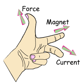
The basic principle behind the working of motor is that when a current carrying wire is placed in a magnetic field it experiences a force. The direction of this force can be determined by Fleming’s left hand rule.

Thus using electrical energy we setup an electric current in a coil
and in an electromagnet. The electromagnet thus behaves like a magnet. The current carrying coil when placed in magnetic field of electromagnet experiences a force. Using suitable arrangement and designing, the coil can be made to rotate.

Construction
A simple electric motor consists of a rectangular coil ABCD of insulated copper wire placed between two opposite poles magnets as shown in the figure. The ends of the coil are connected to two half of a split ring (S1 and S2) attached to the axle. The split rings are connected to two carbon brushes B1 and B2 as shown in the figure. The carbon brushes are connected to a battery through connecting wire and a key (or switch).


©Udvita.org

Working:

First Half Cycle
Let the plane of coil is initially placed horizontally as shown in the figure. The direction of current in the coil is along ABCD. The direction of magnetic field is from North pole to the south pole.
By applying Fleming’s left hand rule on arm AB, the direction of force on arm AB is downward. Similarly the direction of force on arm CD is upward. Under the action of two equal and opposite will make the coil mounted on an axle to rotate anticlockwise.


Second Half Cycle
After half a rotation, arms AB and CD will interchange its position. The split ring S1 is now in contact with brush B2 and the split ring S2 is in contact with brush B1. The direction of current in the coil is now DCBA, reversed as compared to first half cycle. A device which reverses the direction of current in a circuit is called commutator. In electric motor, split rings acts as commutator.


©Udvita.org

By applying Fleming’s left hand rule on arm AB, the direction of force on arm AB is upward. Similarly the direction of force on arm CD is downward. Again under the action of two equal and opposite will make the coil mounted on an axle to rotate anticlockwise.

Commercial motor
A commercial motor consists of an electromagnet instead of permanent magnets. The current carrying coil consists of a large number of turns (in thousands). A soft iron core is used on which the coil is wound.
The soft iron core along with the coil is called the armature.


Electric motor
Image credit-AbnormaalElectric motorCC BY-SA 3.0


Uses of electric motor
Electric motor is used in electric fans, water pumps, mixer, MP3 player, computer etc


Simplest Electric Motor
Watch the Simplest electric Motor video made by our YouTube Channel partner 'Learn n hv Fun'.
The motor is simply made using a copper coil and few neudymium magnets using a 1.5V  electric cell.


Question Bank - Magnetic effects of electric current


1.    Why does a compass needle got deflected when brought near a bar magnet?

2.    Draw magnetic field lines of a bar magnet.

3.    List any two properties of magnetic field lines.

4.    The magnetic field in a given region is uniform. Draw a diagram to represent it.

5.    Consider a circular loop of wire lying in the plane of the table. Let the current pass through the loop clockwise. Apply the right hand rule to find out the direction of magnetic field inside and outside the loop.

6.    Why don’t two magnetic field lines intersect each other?

7.    Explain different ways to induce current in a coil.

8.    State Fleming’s left hand rule.

9.     What is the principle of electric motor?

10.   State the principle of electric generator.

11.   State Fleming’s right hand rule.

12.   State right hand thumb rule.

13.   Name some sources of direct current.

14.   Which sources produces alternating current?

15.   Name two safety measures commonly used in electric circuit and appliances.

16.   What precautions should be taken to avoid the overloading of domestic electric circuit?

17.   An electric oven of a 2kW power rating is operated in a domestic circuit (220 V) that has a current rating of 5A. What result do you expect? Explain.

18.   Define electromagnetic induction.

19.   List three sources of magnetic field.

20.   How does a solenoid behaves like a bar magnet? Can you determine the north and south poles of a current carrying solenoid with the help of a bar magnet? Explain.

21.   When is the force experienced by a current-carrying conductor placed in a magnetic field largest?

22.   Imagine you are sitting in a chamber with your back to one wall. An electron beam, moving horizontally from back wall towards the front wall, is deflected by a strong magnetic field to your right side. What is the direction of the magnetic field?

23.   A coil of insulated copper wire is connected to a galvanometer. What would happen if a bar magnet is

  (i) Pushed into the coil.

  (ii) Withdrawn from inside the coil.

  (iii) Held stationary inside the coil.

24.   Two circular coils A and B are placed closed to each other. If the current in the coil A is changed, will some current be induced in the coil B? Give reason.

25.   State the rule to determine the direction of a

  (i) Magnetic field produced around a straight conductor carrying current.

  (ii) Force experienced by a current carrying straight conductor placed in a magnetic field which is perpendicular to it.

  (iii) Current induced in a coil due to its rotation in a magnetic field.

26.   When does an electric short-circuit occur?

27.   What is the function of an earth wire? Why is it necessary to earth metallic appliances?

28.   What is the effect of inserting a soft iron core inside a current-carrying solenoid? What is this arrangement known as?

29.   What is the capacity of an electric fuse used in (i)lighting circuit (ii) power circuit used in household supply?

30.   State two characteristics of electric fuse wire.

31.   State two ways by which the strength of an electromagnet can be increased.

32.   State three factors on which the magnitude of force on a current carrying –conductor placed in a magnetic field depends. Can this force be zero for some position of the conductor?

33.   Draw the magnetic field lines around a straight conductor carrying current.

34.   Draw the magnetic field lines due to a current-carrying circular wire.

35.   What is solenoid? Draw the magnetic field lines due to a current carrying solenoid.

36.   Compare the magnetic field produced by a bar magnet and a solenoid?

37.   What is the difference between a direction current and an alternating current? How many times does AC used in India change direction in one second?

38.   In what way can the magnitude of induced current be increased?

39.   How does AC differ from DC? What are the advantages and disadvantages of AC over DC?

40.   What is earthing? How does it work as a safety measure?

41.   What is the function of earth wire? Why is it necessary to earth the metallic appliances?

42.   What is the role of fuse used in series with any electrical appliance?

43.   Why should a fuse with defined rating not be replaced by one with a larger rating?

44.   How is the direction of magnetic field at a point determined?

45.   What is the direction of magnetic field at the centre of a current-carrying circular loop?

46.   A magnetic compass shows a deflection when placed near a current carrying wire. How will the deflection of the compass get affected if the cyrrent in the wire is increased? Support your answer with reason.

47.   What does the divergence of magnetic fied lines near the ends of a current carrying straight solenoid indicate?

48.   An electron enters a uniform magnetic field at right anges to it as shown in the figure. In which direction will this electron move? State the principle applied by you in finding the direction of motion of the electron?

49.   What is an electric fuse? How does it function?

50.   A fuse is rated at 8 A, it means:

   (a) It will not work if current is less than 8 A.

   (b) It has a resistance of 8 ohm.

   (c) It will work only if current is 8 A.

   (d) It will burn if current exceeds 8 A.


Electromagnetic Induction

Electromagnetic Induction

The process, by which a changing magnetic field in a conductor induces a current in it, is called Electromagnetic Induction.

Activity 1

1.    Take a coil of wire having many turns.
2.     Connect it to a sensitive galvanometer.
3.     Take a bar magnet and move the north pole of the magnet towards the coil.


Observation: you will observe that galvanometer will give a deflection in one direction (say left).

4.    Now move the north pole of the magnet away from the coil.

Observation: you will observe that galvanometer now give a deflection in opposite direction (now right)

**Similar effect will be observed if we use the south pole of the magnet in the above activity. But the direction of deflection will be reversed.

**Similar effect will be observed if we keep the magnet stationary and move the coil towards or away from the coil.

**When the coil and the magnet are both stationary, there is no deflection in the galvanometer.

Thus whenever there is a relative motion between the coil and the magnet, it induces a current in the coil.


Summary of the activity

POSITION OF THE MAGNET
DEFLECTION IN THE GALVANOMETER
Magnet at rest
No deflection in galvanometer
Magnet moves towards the coil
Deflection in galvanometer in one direction
Magnet is held stationary at same position (near the coil)
 No deflection in galvanometer
Magnet moves away from the coil
Deflection in galvanometer but in opposite direction
Magnet is held stationary at same position (away from the coil)
No deflection in galvanometer
Magnetic is held stationary inside the coil
 No deflection in galvanometer


Activity 2

1.    Take two different coils of copper wire having large number of turns (say 50 and 100 turns respectively). Insert them over a non-conducting cylindrical roll


2.    Connect the coil-1, having larger number of turns, in series with a battery and a plug key.
3.    Also connect the other coil-2 with a galvanometer as shown.
4.    Plug in the key. Observe the galvanometer.
Observation: You will observe that the needle of the galvanometer instantly jumps to one side and just as quickly returns to zero, indicating a momentary current in coil-2.
5.    Disconnect coil-1 from the battery.  Observe the galvanometer.


Observation: You will observe that the needle momentarily moves, but to the opposite side. It means that now the current flows in the opposite direction in coil-2.

Remark on activity 1 and 2

Thus form activity 1 and activity 2 it is clear that we can induce current in a coil either by moving it in a magnetic field or by changing the magnetic field around it. It is convenient in most situations to move the coil in a magnetic field.


The induced current is found to be the highest when

the direction of motion of the coil is at right angles to the magnetic field. In this situation, we can use a simple rule, Fleming's Right Hand Rule, to know the direction of the induced current.

Fleming’s Right Hand Rule


Hold the forefinger, the central finger and the thumb of the right hand perpendicular to each other so that the forefinger indicates the direction of the field, and the thumb is in the direction of motion of the conductor. Then, the central finger shows the direction of the current induced in the conductor.


Force on a current carrying wire

FORCE ON A CURRENT CARRYING CONDUCTOR PLACED IN A MAGNETIC FIELD

Any current carrying conductor when kept in magnetic field experiences a force. 
Watch a youTube video below to observe how a current carrying wire experiences a force when kept in a magnetic field. 


Video courtesy : Learn n hv fun YouTube Channel (A volunteer member of the website)


The direction of force is given by FLEMING’S LEFT HAND RULE.

ACTIVITY


1.   Take a small aluminium rod AB.
2.   Suspend it horizontally with the help of connecting wires from a stand.
3.   Place a strong horseshoe magnet in such a way that the rod is between the two poles with the field directed upwards.
4.   When current is passed in the rod from B to A, the rod gets displaced towards left.
5.   On reversing the direction of the current, the rod gets deflected towards right.

The deflection in the rod is caused by the force acting on the current carrying rod when placed in a magnetic field.
The displacement of the rod is largest (or the magnitude of the force is the highest) when the direction of current is at right angles to the direction of the magnetic field. In such a condition we can use a simple rule to find the direction of the force on the conductor.

FLEMING’S LEFT HAND RULE


Stretch the forefinger, the central finger and the thumb of your left hand mutually perpendicular to each other. If the forefinger shows the direction of the field and the central finger that of the current, then the thumb will point towards the force or direction of motion of the conductor.

FORCE ON A MOVING CHARGE PARTICLE IN A MAGNETIC FIELD


A current carrying conductor experiences a force when placed in a magnetic field. As current is simply flowing of charges, it implies that moving charged particles also experiences a force in a magnetic field.
The direction of the force on a moving positive charge is given by Fleming’s Left hand rule (discussed above).

Application of force experienced when placed in a magnetic field
Devices that use current-carrying conductors and magnetic fields include electric motor, loudspeakers, microphones and measuring instruments.


Solenoid

SOLENOID

A coil of many circular turns of insulated copper wire wrapped closely in the form of a cylinder is called a solenoid.


A solenoid

MAGNETIC FIELD DUE TO CURRENT IN A SOLENOID


1.   The magnetic field due to a solenoid is very much similar to that of a bar magnet. The pattern of the magnetic field lines around a current-carrying solenoid is similar to that of bar magnet. Just like a bar magnet, one end of the solenoid behaves as a magnetic north pole, while the other behaves as the South Pole. 
2.   The field lines inside the solenoid are in the form of parallel straight lines. This indicates that the magnetic field is the same at all points inside the solenoid. That is, the field is uniform inside the solenoid.

PRACTICAL USE OF SOLENOID

A strong magnetic field produced in a solenoid can be used to magnetize a piece of magnetic material when it is placed within the coil, which is carrying electric current.


ACTIVITY

1.   Take a iron nail.
2.   Wrap a coil of insulated copper wire on it.
3.   Connect the coil to a battery through a switch.
4.   As the current is passed through the coil, the nail, which acts as a core inside the solenoid, gets magnetized.
The magnet so formed is called an electromagnet.

ELECTROMAGNET

An electromagnet consists of a long coil of insulated copper wire wound on a soft iron core.


TEMPORARY MAGNET

If the core of the solenoid is taken of soft iron and electric current is passed through the solenoid, the soft iron core is temporarily magnetized which means when the current is switched off soft iron loses its magnetic properties. An electromagnet is a temporary magnet.

PERMANENT MAGNET

If the core of the solenoid is taken of carbon steel, chromium steel, cobalt and tungsten steel and certain alloys like Nipermag (alloy of iron, nickel, aluminium and titanium) and ALNICO (alloy of Aluminium, nickel and cobalt) and a strong electric current is passed through the coil then these materials become permanently magnetized.


Uses of permanent magnets


Such permanent magnets are used in microphones, loudspeakers, electric clocks, ammeter, voltmeter and speedometer, etc.


Circular coil

MAGNETIC FIELD DUE TO A CURRENT CARRYING CIRCULAR WIRE


Using Right Hand thumb rule, the magnetic field lines at every point of the circular wire are in the form of concentric circles with wire as the center. These magnetic field lines become larger and larger as we move away from the wire. Just at the center of the coil, magnetic field lines are almost straight. By applying Right hand rule, it is easy to check that every section of the wire contributes to magnetic field lines in the same direction within the loop.


Factors on which the magnetic field at the centre of the circular loop depends upon

1.   Directly proportional to the current flowing in the loop. 
2.   Inversely proportional to the radius of the circular wire.
3.   Directly proportional to the number of turns of the circular loop. This is because the current in each circular turn has the same direction, and the field due to each turn then just adds up.


Magnetic field due to current carrying straight conductor

Magnetic field around a current carrying straight conductor

Activity

1. Take a straight wire AB and pierced it through a horizontal cardboard such that wire AB is vertical.
2.   The ends of the wire AB are connected to a battery.
3.   Place some iron fillings on the cardboard.
4.   Switched the key on.
5.   Gently tap the cardboard.
6.   The iron fillings arrange themselves in concentric circles around the wire.
7.   This shows that magnetic field lines are concentric circles. The circles become larger and larger as we move away from the wire.

Watch a related video from YouTube.


Direction of field lines- Right Hand thumb rule

The direction of field lines due to a current carrying wire can be determined by using Right Hand Thumb Rule (Or Right Hand Grip Rule). 

Imagine that you are holding a current carrying wire in your right hand such that the thumb is stretched along the direction of the current, then, the fingers will wrap around the conductor in the direction of the field lines of the magnetic field.


Factors on which the magnetic field at a distance from the straight wire depends on

1.   Directly proportional to the current flowing in the wire.
2.   Inversely proportional to the distance from the wire.


Magnetic field and field lines

Oersted’s Experiment

(Relation between electricity and magnetism)

The first evidence of any connection between Electricity and magnetism was established by Hans Christian Oersted. He accidentally discovered that as he laid a wire carrying an electric current near a magnetic compass needle, it got deflected as if acted upon by a magnet.


This observation led to the discovery that when current passes through a conductor, magnetic field is produced around it.

Magnetic field

The space around a magnet or a current carrying conductor, in which the force of attraction or repulsion can be experienced, is called a magnetic field.

Demonstration of magnetic field lines (Iron-filings pattern)

1.  Take a bar magnet and placed it on a cardboard.
2.  Sprinkle some iron-fillings around the magnet.
3.  Tap the cardboard gently.
4.  Iron fillings arrange themselves in a pattern as shown in figure.


Conclusion: This pattern demonstrates that under the influence of magnetic field, the fillings align themselves along the magnetic field lines.

Tracing of magnetic field lines of a bar magnet

1.   Place a bar magnet on a sheet of paper.
2.   Bring the compass near the north pole of the magnet.
3.   The needle will deflect such that its south pole points towards North Pole of the bar magnet.
4.   Mark the position of two ends of needle.
5.   Move the compass so that its south end occupies the position previously occupied by the north end.
6.   Again mark the new position of ends of needle.
7.   Repeat step 5 and 6 till you reach the south pole of the magnet.
8.   Join the points marked to get a smooth curve, which represents a field line.


Magnetic field lines

Magnetic field lines are the imaginary lines used to represent a magnetic field. A field line is the path along which a hypothetical free north pole would tend to move. The direction of the magnetic field at a point is given by the direction that a north pole placed at that point would take.

Properties of Magnetic field lines

1.   Outside the bar magnet, the magnetic field lines originate from the north pole of a magnet and end at its south pole.
2.   Inside the bar magnet, field lines move from South Pole of the magnet to the North Pole.
3.   Magnetic field lines always form closed curves.
4.   The regions, where field lines are closer, the field is strong and the regions, where the field lines are farther apart, the field is weak.
5.   The direction of the magnetic field is taken to be the direction in which a north pole of the compass needle moves inside it.
6.   The magnetic field lines never cut each other. In case, two field lines intersect each other at a point, then it will mean that at the point of intersection, the magnetic needle would point in two different directions, which is not possible.


MCQ on magnetic effect

MAGNETIC EFFECTS OF ELECTRIC CURRENT

Multiple Choice Questions
1. Choose the incorrect statement from the following regarding magnetic lines of field
(a) The direction of magnetic field at a point is taken to be the direction in which the north pole of a magnetic compass needle points
(b) Magnetic field lines are closed curves
(c) If magnetic field lines are parallel and equidistant, they represent zero field strength
(d) Relative strength of magnetic field is shown by the degree of closeness of the field lines

2. If the key in the arrangement is taken out (the circuit is made open) and magnetic field lines are drawn over the horizontal plane ABCD, the lines are


 (a) concentric circles
(b) elliptical in shape
(c) straight lines parallel to each other
(d) concentric circles near the point O but of elliptical shapes as we go away from it

3. A circular loop placed in a plane perpendicular to the plane of paper carries a current when the key is ON. The current as seen from points A and B (in the plane of paper and on the axis of the coil) is anti clockwise and clockwise respectively. The magnetic field lines point from B to A. The N-pole of the resultant magnet is on the face close to


(a) A
(b) B
(c) A if the current is small, and B if the current is large
(d) B if the current is small and A if the current is large

4. For a current in a long straight solenoid N- and S-poles are created at the two ends. Among the following statements, the incorrect statement is
(a) The field lines inside the solenoid are in the form of straight lines which indicates that the magnetic field is the same at all points inside the solenoid
(b) The strong magnetic field produced inside the solenoid can be used to magnetise a piece of magnetic material like soft iron, when placed inside the coil
(c) The pattern of the magnetic field associated with the solenoid is different from the pattern of the magnetic field around a bar magnet
(d) The N- and S-poles exchange position when the direction of current through the solenoid is reversed

6. Commercial electric motors do not use
(a) an electromagnet to rotate the armature
(b) effectively large number of turns of conducting wire in the current carrying coil
(c) a permanent magnet to rotate the armature
(d) a soft iron core on which the coil is wound

5. A uniform magnetic field exists in the plane of paper pointing from left to right as shown in Figure. In the field an electron and a proton move as shown. The electron and the proton experience


(a) forces both pointing into the plane of paper
(b) forces both pointing out of the plane of paper
(c) forces pointing into the plane of paper and out of the plane of paper, respectively
(d) force pointing opposite and along the direction of the uniform magnetic field respectively

7. In the arrangement shown in there are two coils wound on a non-conducting cylindrical rod. Initially the key is not inserted. Then the key is inserted and later removed. Then


(a) the deflection in the galvanometer remains zero throughout
(b) there is a momentary deflection in the galvanometer but it dies out shortly and there is no effect when the key is removed
 (c) there are momentary galvanometer deflections that die out shortly; the deflections are in the same direction
(d) there are momentary galvanometer deflections that die out shortly; the deflections are in opposite directions

8. Choose the incorrect statement
(a) Fleming’s right-hand rule is a simple rule to know the direction of induced current
(b) The right-hand thumb rule is used to find the direction of magnetic fields due to current carrying conductors
(c) The difference between the direct and alternating currents is that the direct current always flows in one direction, whereas the alternating current reverses its direction periodically
(d) In India, the AC changes direction after every 150 second

9. A constant current flows in a horizontal wire in the plane of the paper from east to west as shown in figure. The direction of magnetic field at a point will be North to South

(a) directly above the wire
(b) directly below the wire
(c) at a point located in the plane of the paper, on the north side of the wire
(d) at a point located in the plane of the paper, on the south side of the wire

10. The strength of magnetic field inside a long current carrying straight solenoid is
(a) more at the ends than at the centre
(b) minimum in the middle
(c) same at all points
(d) found to increase from one end to the other

11. To convert an AC generator into DC generator
(a) split-ring type commutator must be used
(b) slip rings and brushes must be used
(c) a stronger magnetic field has to be used
(d) a rectangular wire loop has to be used

12. The most important safety method used for protecting home
appliances from short circuiting or overloading is
(a) earthing
(b) use of fuse
(c) use of stabilizers

(d) use of electric meter